04 September 2012

Warning! One Million Ohms

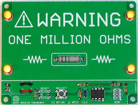
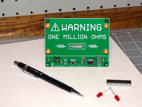
An electronic version of an old joke known among physicists and engineers.


Amuse your friends and confuse your enemies! Keep the uninitiated away from your workbench or desk and out of your lab!
  • Great conversation piece or gag gift
  • Big, scary 1,000,000 Ω resistor in the middle of the board
  • Pre-programmed AVR microcontroller (ATtiny85)
  • Arduino-compatible, hackable open-source hardware and software Can be re-programmed with an ICSP programmer, using either the Arduino integrated development environment or WinAVR
  • Runs on two AA batteries (not included)
Pressing the SELECT button turns the circuit on and causes the red LEDs to flash. To change the flashing speed and pattern, press SELECT again. Hold SELECT down to turn the circuit off, or it will automatically turn itself off after five minutes.

17 March 2012

Arduino Timezone and DST Library

The Timezone library facilitates time zone conversions and automatic daylight saving (summer) time adjustments. This is accomplished by setting a Real Time Clock (RTC) to Universal Coordinated Time (UTC) and then converting UTC to the correct local time, whether it is daylight saving time (a.k.a. summer time) or standard time.

The Timezone library is designed to work in conjunction with the Arduino Time library at http://www.arduino.cc/playground/Code/Time. To download and use the Timezone library, including documentation and example sketches:


  • Go to https://github.com/JChristensen/Timezone/downloads and download the file in the compressed format of your choice (zip or tar.gz) to a convenient location on your PC.
  • Uncompress the downloaded file. This will result in a folder containing all the files for the library, that has a name similar to "JChristensen-Timezone-42e98a7".
  • Rename the folder to just "Timezone".
  • Copy the renamed folder to the Arduino sketchbook\libraries folder.
  • Read the ReadMe.txt file!
  • 07 February 2012

    A high-tech night light

    Often I find myself working on small projects that might be categorized as silly and/or impractical. However, my aim is usually to learn something new and to have a little fun in the process. So here is an example of such a project that I've been tinkering with recently.

    Worlds highest-tech night light?  The two AA cells are underneath and connect via the connector on the upper left.


    This project is a night light that just consists of a common 5mm LED for the light, an ATmega328P microcontroller, two AA cells, and a minimum of other parts. The twist is that the LED turns on at sunset and off at sunrise, adjusting its on and off times automatically day by day throughout the year, including adjustment for daylight saving time. I also added a piezo transducer to make some noise at sunrise and sunset. This was mostly a debugging aid to make it easier to check whether it was turning on and off at the right times. This project has several features of interest:
    1. Timer/Counter2 is clocked from a 32.768kHz crystal and configured to generate an interrupt every 8 seconds.
    2. The interrupt service routine (ISR) that handles these interrupts comprises a software real-time clock (RTC) that tracks hour, minute, second, day, month, and year (and adjusts for leap year).
    3. A friend found a function on the web that calculates sunrise and sunset times given day of the year, latitude, and longitude. (I tweaked it a bit, I think that I improved it some.) Combining this with the RTC makes it quite straightforward to turn the LED on and off at the appropriate times. (But I definitely do not get all of this astronomical right ascension and declination stuff!)
    4. I had previously written code to automatically adjust for daylight saving time, so it was easy enough to include (feature creep!) The rules which determine when DST starts and ends are stored in EEPROM. There is a small separate sketch to store the DST rules.
    5. Since the project runs on batteries, we want to conserve power. So in between interrupts, the MCU puts itself into Power Save mode, which keeps Timer2 running so that the RTC continues to keep accurate time, but powers off most of the other systems. An interesting point here is that the MCU can sleep regardless of whether the LED is on or off. Once the pin driving the LED is set, it retains its state while the MCU sleeps. While sleeping, with the LED off, the project draws right around one microampere. The Timer2 interrupt every 8 seconds serves to wake the MCU, update the RTC, and switch the LED on or off if appropriate. I haven't kept track of how long the battery will last, but I'm guessing at least a few weeks.
    When not sleeping, the MCU is clocked from the internal RC oscillator, running at 1MHz. Because of this, the sketch needs to be uploaded from the Arduino IDE using an ICSP programmer (I use Adafruit's USBtinyISP).

    I added the following entry to the Arduino boards.txt file, which is used for this project. Note the fuse byte settings. The extended fuse byte sets the brown-out detector level to 1.8V (to keep the MCU in reset if the battery gets too low), and the low fuse byte is the same as the factory default setting to give the 1MHz system clock.

     uno1.name=Arduino Uno ICSP @ 1MHz
     uno1.upload.using=arduino:usbtinyisp
     uno1.upload.protocol=stk500
     uno1.upload.maximum_size=30720
     uno1.upload.speed=19200
     uno1.bootloader.low_fuses=0x62
     uno1.bootloader.high_fuses=0xD6
     uno1.bootloader.extended_fuses=0x06
     uno1.bootloader.path=atmega
     uno1.bootloader.file=ATmegaBOOT_168_atmega328.hex
     uno1.bootloader.unlock_bits=0x3F
     uno1.bootloader.lock_bits=0x0F
     uno1.build.mcu=atmega328p
     uno1.build.f_cpu=1000000L
     uno1.build.core=arduino

    Even though the project works well, it's not what I'd call a practical project that will ever get past the breadboard stage. It ended up with a fair amount of code, which seems like definite overkill for a crummy night light (wouldn't a photocell be more straightforward?) But I figure why not, if I learned some things and had a good time with it. I hope you enjoy it too!

    The code and schematic for this project are available on github.

    06 September 2011

    Arduino “Breadboard Helpers”


    I think that everyone should breadboard an Arduino at least once (one approach here, another here). It’s a great learning experience that does a lot to de-mystify all that circuitry, or perhaps more correctly, it shows just how simple “all that circuitry” can really be.

    For many projects, using breadboards makes a lot of sense to me. But after three or four times, it gets pretty repetitious, not to mention time-consuming and error-prone, putting all the basic wiring in place for the MCU.  I especially hate the FTDI and ICSP programming headers. My memory being what it is, I always have to refer to some cheat sheet to figure out all six connections for each!

    I had the idea of using a pair of small breakout boards to make the repetitious part easier and allow me to get to the interesting part of the project sooner.  One board provides the FTDI header and the other provides the ICSP header.  I call them “Breadboard Helpers” (with apologies to Hamburger Helper ™).  With the first version of the boards, I concentrated mostly on the programming headers, although I added a reset button to the FTDI board and the Arduino “Pin 13” LED to the ICSP board.

    Then I thought that I could expand the idea a bit and make things even easier.  So the second versions of the boards have the following features:

    FTDI Breadboard Helper

    ICSP Breadboard Helper
    • ICSP programming header
    • Arduino “Pin 13” LED and current-limiting resistor
    • AVcc bypass capacitor
    • Power supply bypass and filter capacitors
    • MCU power and ground connections
    • Under ¾ square inch

    With Breadboard Helpers, I can literally breadboard an Arduino in less than a minute.  I don’t have to remember how to wire the programming connections, or worry about mixing up the power pins, RX/TX, or MOSI/MISO.  Plus, I end up with a much neater breadboard and more room for the rest of my project.

    An Arduino-compatible made with Breadboard Helpers

    The picture below is as compact as I think I can manage to breadboard an Arduino; 46 of the 5-position tie points are used, only leaving 14 available on this small breadboard. There’s only room for an 8-pin DIP device. I didn’t watch the clock, but I’d bet it took me the better part of an hour.

    Identical circuit as in the above picture, made with individual components.
    Not much room left on a small breadboard.

    A couple things to note with Breadboard Helpers.  First, if you’re doing ICSP programming, you will need one wire to go from the RST pin on the ICSP board to MCU pin 1, the reset pin (this is the green wire in the first picture above).

    Second, I have two kinds of breadboards.  The larger ones have the holes in the power rails aligned with the holes on the main part of the breadboard.  The smaller breadboards have the holes in the power rails staggered relative to the main part.  Breadboard Helpers have two positions for the power pins, to allow them to be built to work with one type breadboard or the other.

    Breadboard Helpers are also flexible.  Several of the parts can be eliminated if you don’t plan to use them, and can be added later if needed.  Not doing ICSP programming?  Leave the 2x3 header off.  Don’t care about the LED?  Leave it and its resistor off.  If you’re using a resonator that has built-in capacitors, then the crystal loading capacitors aren’t needed of course.  If you don’t have any worries about power supply filtering, the small electrolytic capacitors can be eliminated; however, I do recommend retaining the 100nF bypass capacitors.

    If you’d be interested in Arduino Breadboard Helpers, leave me a comment.  If there’s enough interest, I might put a small run of kits together (soldering required!).

    If you'd like to roll your own, the Eagle files are available on github, and a bill of materials with all the components needed, including the microcontroller and a breadboard, is available on the Mouser web site.  Note that if you order the microcontroller from Mouser, it will need to be programmed with an Arduino bootloader.
    21 July 2011

    Arduino Thermocouple Library

    This is a very simple library that I wrote earlier this year, I've just now added a couple example sketches and some documentation, so that folks might actually stand a chance of figuring it out.

    The library works in conjunction with the standard Arduino SPI library to interface one or more MAX6675 Cold-Junction-Compensated K-Thermocouple-to-Digital Converters from Maxim Integrated Products.

    I've posted the library on github, click the Downloads button to download the library, examples, and ReadMe as a .zip or .tar.gz file.

    Questions, comments, suggestions, gripes, etc., always welcome!

    02 May 2011

    The Evil Arduino

    I can't help but like a place called Evil Mad Science. I picked up a couple of their ATmegaXX8 Target Boards and a couple ATtiny2313 Target Boards with the intention of using them to do ICSP programming. I realized that with the addition of a few common components, the ATmegaXX8 Target Board could do that and also be used as a basic Arduino clone. EMS also has a good price on Zero-Insertion Force (ZIF) sockets which are great if you're swapping the MCUs in and out a lot.

    So this is kind of a simple-minded project and I'd be surprised if it was an original idea, but I thought I'd show how I used EMS' "fine DIY and open source hardware" to make a simple Arduino clone. Just a fun little project that can be tossed together in about an hour.

    On the other hand, a person could just go with EMS' Diavolino kit. At $13, it could well be cheaper than the target board approach, especially if you don't have the incidental components laying around as I did. And the Diavolino also has the Arduino form factor. So it depends what you want. The target board approach has more of a DIY flavor as opposed to a kit.

    Parts list:

    C1,2  18pF ceramic, or as needed to match crystal*
    C3-6  100nF ceramic
    C7    10uF 16V electrolytic
    IC1   ATmega328P
    J1    2x3 ICSP HEADER
    J2    6x1 FTDI HEADER
    LED1  Red garden-variety (Pin 13 LED)
    LED2  Green garden-variety (Power LED)
    Q1    16MHz*
    R1    10K
    R2,3  1K
    S1    SPST MC NO Tact switch
    n/a   ZIF or other 28-pin DIL socket
    n/a   Evil Mad Science ATmegaXX8 Target Board

    *EMS sells a 16MHz Crystal and Capacitor Set, which is what I used, but of course they could also be purchased individually, or a resonator could be used instead.


    Schematic

    Arduino-compatible built on EMS target board

    Action shot ;-)

    28 April 2011

    A "Minimal" Arduino/XBee/Pachube Sensor Network

    One or two people have asked in online forums for code from my sensor network, and while I'm usually happy to share, it's full of a lot of extraneous stuff (RTCs, NTP, displays, thermocouples) that might not be of interest to everyone, but more importantly, that probably only obscures the fundamentals of XBee networking and communicating with Pachube.

    So with that in mind, I cut out the extraneous stuff, and just left the bare essentials: A remote sensor unit which transmits a single reading from a photocell once per minute to a base unit which connects to the internet and forwards the data on to Pachube.

    Bill of materials -- Base unit:
    (1) Arduino Uno, Through-hole or SMD edition
    (1) Arduino Ethernet shield
    (1) XBee ZB low power Zigbee Module, Digi Product ID XB24-Z7CIT-004, XB24-Z7WIT-004, XB24-Z7SIT-004, or XB24-Z7UIT-004 (these differ only in the antenna, they are functionally equivalent)
    (1) Adafruit Industries XBee Adapter
    (1) LED for heartbeat (optional)
    (1) 330-ohm resistor for heartbeat LED (optional)

    XBee configuration:
    • Load the Zigbee Coordinator API firmware (I'm using Version 2170).
    • Set the PAN ID as desired, to match that of the sensor unit(s).
    • Set API mode 2 (AP=2).
    • Set baud rate to 9600.

    Bill of materials -- Remote unit:
    (1) Arduino Uno or similar (Through-hole, SMD edition, Boarduino, etc.)
    (1) XBee ZB low power Zigbee Module, Digi Product ID XB24-Z7CIT-004, XB24-Z7WIT-004, XB24-Z7SIT-004, or XB24-Z7UIT-004.
    (1) Adafruit Industries XBee Adapter
    (1) CdS photocell
    (1) 10K resistor

    XBee configuration is same as above, except:
    • Load the Zigbee Router API firmware (I'm using Version 2370).

    Here are the sketches.  Unzip into the Arduino Sketchbook folder.  Before uploading, be sure to disconnect the XBee from Arduino pin 0.  Also be sure to enter your MAC, IP, and Pachube API key in the base station main module, and your Pachube feed number and the address of your network coordinator XBee in the main module for the remote unit.

    Here is the Pachube feed. Pretty boring, but at least you can see that it does work. Not sure how long I'll leave it running, probably until I need the parts for something else!  Feedback and questions welcome!

    Note that in the following wiring diagrams, the XBees plug into the Adafruit adapter, which in turn plugs into the breadboard. The XBee pins do not (in fact, cannot, spacing is different) connect to the breadboard.  The adapter plugs into the breadboard, this is represented by the 10-pin header below the XBee.

    Wiring the base unit


    Wiring the remote unit

    My base unit

    My remote unit (using a Boarduino)

    08 February 2011

    Easy NiMH discharge curves

    This post is a bit of an aside, or at least it started out that way.  I thought it worth noting though, because it's a good example of how quickly and easily a new Arduino/Pachube application can be put together, once you have some basics in place.

    A friend was having some difficulty with some older NiMH rechargeable batteries (actually AA cells).  He'd charge them up, but when he put them in his camera it would immediately complain that the batteries were low, and it wouldn't turn on.  The batteries seemed OK when checked with a voltmeter, reading 1.4V or a little better (the nominal voltage for NiMH cells is 1.2V).  My friend was aware that batteries are best tested under load, and I gave him a few resistors for that purpose, and he went off to try again.

    In the meantime, I was looking at my recently-completed XBee/Arduino/Pachube lashup (see prior post) and a light went on.

    I wired up two NiMH cells with resistors for loads, connected them to two analog inputs on the Arduino, added a few lines of code to the Arduino sketch, and literally within 10 or 15 minutes I had Pachube collecting the voltage data once per minute (in addition to the temperature data that I was already collecting).  It's taken me a lot longer to write this post than it did to get the thing working in the first place!

    Now I could produce nice discharge curves for two batteries simultaneously.  It was just a matter of popping them into the battery holders, then waiting for 8 or 10 hours while they discharged and Pachube collected the data.  In the end this gives a heck of a lot better picture of what's going on than could have been accomplished with a voltmeter, and with a lot less effort!

    This first chart shows two cells that I had.  The first was relatively new (~8 months old), and the other a few years old, and while I no longer used it in my camera, it still seemed to work OK in my old iRiver MP3 player.  You can see Cell A held 1.2V for six hours or so, but Cell B dropped below 1.2V after about only an hour.  What surprised me is that the curves aren't that different, just shifted down for the older battery.  If you do the math on the mAh capacity, it comes out pretty close!


    The second chart shows two of my friend's cells that wouldn't work in the camera.  Cell C looks similar to my Cell B, but Cell D drops below 1.2V almost immediately, and after an hour, is below 1.1V.  Note the sharp initial drop in voltage.  This leads me to suspect that as these cells age, their internal resistance goes up, while overall capacity may only decline modestly.  This is contrary to my gut feel; when a battery doesn't work I think it's dead, empty, out of capacity.  Actually these older batteries might work OK in devices that aren't terribly voltage-sensitive.  Obviously the cameras watch the voltage pretty closely and let you know about it when it drops only a few tenths of a volt.  But consider the challenge: You need to know you're running low far enough in advance of the knee in the curve, because things go south in a hurry then.  And the camera has to make some sort of assumption about the quality/age of the cells.  Or maybe the camera people are just in cahoots with the battery companies ;-)  A 5-ohm load was used on all cells.