In this post I describe how to build an XBee-based wireless sensor network that feeds data to the
GroveStreams Data Analytics Platform. I've been using GroveStreams for a couple years now and I am very impressed. The GroveStreams platform has features and power far beyond other "IoT" data services that I have tried. Perhaps even more impressive is how eager the GroveStreams team is to work with their users. User input frequently results in improvements to the platform, and usually quite rapidly at that. GroveStreams delivers a great service, great performance, and they are intensely focused on their customers.
GroveStreams accounts are free, up to certain levels of utilization; above this, rates seem quite reasonable.
See the site for details.
This project consists of two network nodes, connected by a ZigBee mesh network implemented with
XBee ZB modules (f.k.a. Series 2). One node is the web gateway. Its XBee is configured as the network coordinator. The gateway forwards data sent to it by other nodes to the GroveStreams service via an Ethernet shield.
The other node is a sensor node; its XBee is configured as a router. This node uses a simple analog temperature sensor and sends the data to GroveStreams via the gateway node. Multiple copies of the sensor node are easily added to the network. These can have the same sensor, or with additional programming, other sensors could be added.
Hardware required for this project
(2)
Arduino Uno boards
(1)
Arduino Ethernet shield
(2) XBee ZB modules (I use part no.
XB24-Z7WIT-004 with the wire antenna)
(2)
Adafruit XBee Adapter kits
(1)
Adafruit FTDI Friend (used to configure the XBees with XCTU)
(1) USB A Male to Mini B cable to connect the FTDI friend to a computer
(2) Yellow LEDs (use any common 3mm or 5mm LED)
(2) Red LEDs (ditto)
(4) 330-ohm resistors (anything between 220 ohms and 1000 ohms should be OK)
(1) 100nF ceramic capacitor
(1)
Analog Devices TMP36 temperature sensor
Breadboards, jumper wires, USB and Ethernet cables, power supplies, etc.
Step-by-step instructions
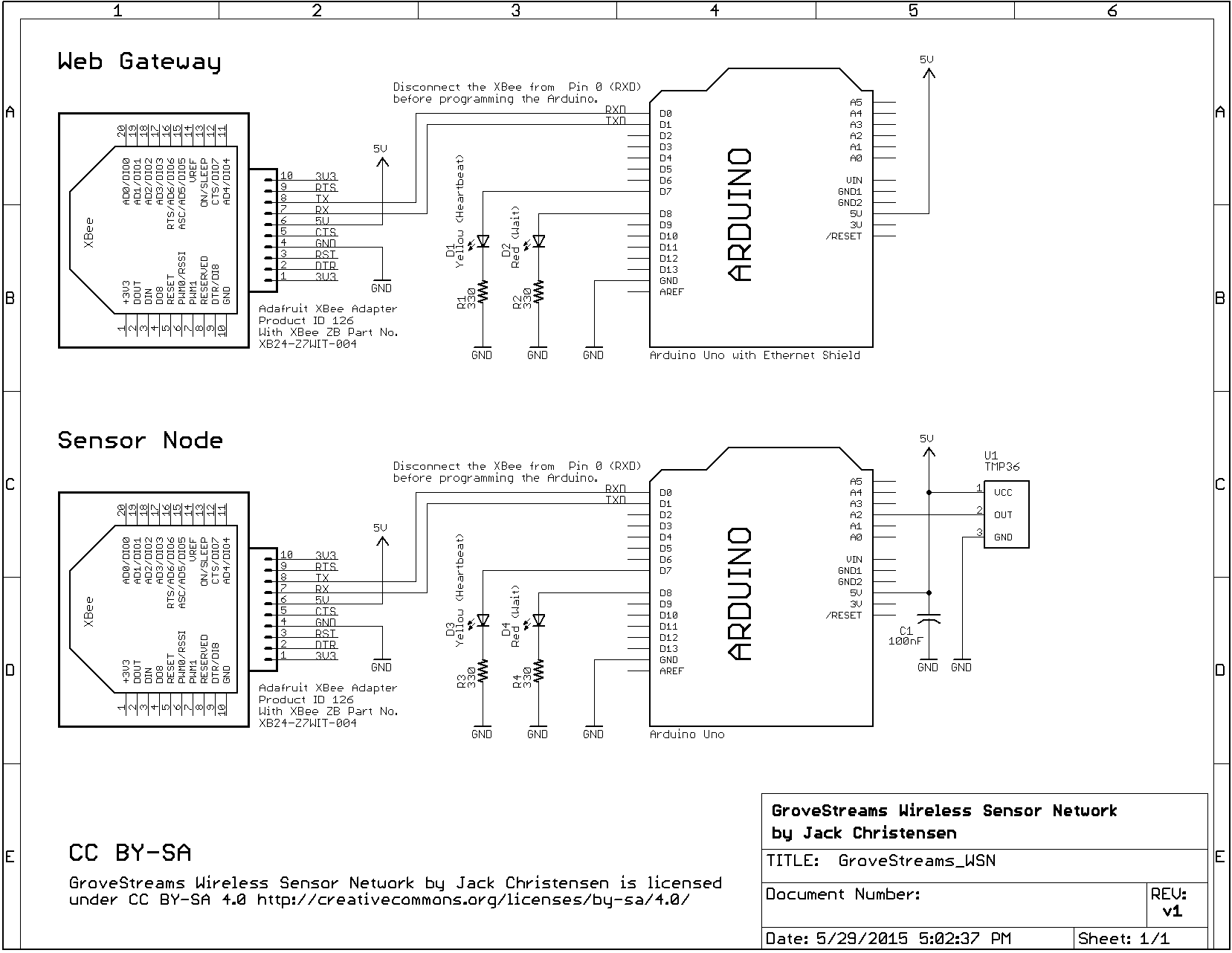
- Build the Gateway and Sensor nodes per the schematic diagram.
 |
| Gateway Node |
 |
| Sensor Node |
- Download and install the XBee Configuration and Test Utility software (XCTU) from digi.com (version 6.2.0 is current as of this writing).
- If you have not used FTDI on your computer before, install the FTDI drivers.
- Install one XBee in an Adafruit XBee adapter. Using the FTDI Friend, connect it to the computer with a USB A-to-Mini-B cable.
 |
| Configuring an XBee with Adafruit's FTDI Friend |
- Download the latest Coordinator API firmware (21A7 as of this writing) to the XBee. Then, configure the ID, NI, BD, and AP parameters as described in the gsGateway example sketch. (The PAN ID can be any number you like; all XBees on the same network must have the same PAN ID. However, I do recommend a non-zero value.)
- Repeat with the other XBee, except download the latest Router API firmware (23A7 as of this writing) and set the four parameters as described in the gsSensor example sketch.
- Install the Coordinator XBee in the Gateway node and the Router XBee in the Sensor node.
- On both the Gateway and Sensor nodes, temporarily disconnect Arduino Pin 0 from the XBee to allow programming. (Since the XBee connects to the Arduino's serial port, it must be disconnected from the RXD pin to allow the Arduino to be programmed via the bootloader.)
- Now go to the GroveStreams web site and create an account. This involves a verification email which should be a familiar process. Once the account is verified, log in and you should see the following message that offers to create an Organization.
 |
| After initial GroveStreams Sign-In |
Let's digress here for a very quick and incomplete primer on some GroveStreams terminology. An Organization is a container for one or more Components. A Component can represent a physical object in the real world. For this project, the Gateway node will be one Component and the Sensor node will be another. Components in turn contain one or more Datastreams, which contain the actual data sent to the GroveStreams site, for example by our sensor. Keep these concepts in mind for now and we'll see how it all fits together shortly.
- Continuing on, respond to the message by clicking Yes to create an Organization. Give it any name you like, then click the Create Organization button.
 |
| Creating an Organization |
- Now we see the GroveStreams start page which lists our Organizations, of which there should be only one, namely the one we just created.
 |
| GroveStreams Start Page |
- Click on the Organization name to open the GroveStreams Observation Studio, which is the main interface to configuring and observing everything in GroveStreams. On the left, note there is a folder for Components, but if the little triangle is clicked, the folder doesn't expand, since no components have been created yet. We can create Components from Observation Studio, but GroveStreams also has a handy feature to create Components automatically when data is first received. Being mostly lazy, we'll use that method for this project.
 |
| GroveStreams Observation Studio |
- Next click on the yellow lock "API Keys" icon near the top right. This will open a dialog that allows keys to be displayed. Our Gateway node needs a key so that GroveStreams can validate it and associate the incoming data with our Organization. Check the box, "Feed Put API Key (with auto-registration and request stream rights)", then click View Secret Key.
 |
| API Keys Dialog |
- In the dialog box that appears, use the mouse to select the key. Press Ctrl-C to copy it to the clipboard, then open Notepad or other convenient application and press Ctrl-V to paste the key. We'll use it shortly, but for now just close the API Secret Key dialog box and the API Keys dialog box.
- We are almost ready to program the Gateway and Sensor nodes. But first we need to install the prerequisite libraries. If you are not familiar with installing libraries, please click this link.
Install each of these libraries:
http://github.com/JChristensen/GroveStreams
This library manages the connection to the GroveStreams web site, allows data to be sent, etc.
http://github.com/JChristensen/gsXBee
This library handles interface to the XBees.
http://github.com/andrewrapp/xbee-arduino
An essential library for working with XBees in API mode.
http://arduiniana.org/libraries/streaming/
A very convenient alternative to Serial.print(). (I don't know why it's not part of the Arduino core.)
- Start the Arduino IDE and open the gsGateway example sketch from the GroveStreams library (File > Examples > GroveStreams > gsGateway). Change this line of code by pasting in the API key that was copied earlier. (You may also want to change the MAC address on the following line, but chances are that the existing one will work fine.)
- Upload the modified gsGateway sketch to the Gateway node. Disconnect the Gateway node. Reconnect Pin 0 to the XBee.
- Open the gsSensor example sketch (File > Examples > GroveStreams > gsSensor) and upload it to the Sensor node. No code changes are needed. Disconnect the Sensor node. Reconnect Pin 0 to the XBee.
- Connect the Gateway node to your LAN with an Ethernet cable. Apply power to the Arduino. After several seconds, the red wait LED should blink once and the yellow heartbeat LED should begin blinking on and off. Upon startup or reset, the Gateway sends a single message to GroveStreams. Go to the GroveStreams Observation Studio and there should now be a Component named "Coord" created for the Gateway/Coordinator node. This may take several seconds; if you don't see it, try refreshing the web page. Expand the Coord Component and one datastream named "msg" should be visible. This is the startup message sent by the Gateway.
 |
| Coord Component created, Startup message sent |
- Connect power to the Sensor node. The first data will be sent in one minute, then at one minute intervals thereafter. Wait at least a minute, then refresh the Observation Studio web page and the Sensor node should now be visible as Component "TMP36a". It has three datastreams: "s" which is a sequence number, "C" which is the temperature in Celsius, and "rss" which is the received signal strength at the Gateway XBee. ("rss" is added by the Gateway node. Note that in larger XBee networks, several hops may occur between source and destination nodes. The RSS value only represents that of the last hop.)
 |
| TMP36a Sensor Component created |
Both nodes write diagnostic information to the serial port; open the Arduino serial monitor or other terminal program at 115,200 baud to observe this information.
Concluding remarks
This has been a long post but it's basically a cookbook approach and only scratches the surface. I hope it will be a starting point for further exploration into both GroveStreams and wireless sensor networks. GroveStreams has much more functionality than I have mentioned so far. Dashboards can display and aggregate data in many different ways, events can be defined to key off certain data values and cause various alerts to be sent, and derived streams can perform various calculations on data. For instance, GroveStreams can easily convert the temperature data sent by the Sensor node from Celsius to Fahrenheit; it would not be necessary to do this in the microcontroller firmware.
I also have not elaborated on the XBee node naming convention. The XBee Node Identifiers (NI) need to start with a one- to eight-character name. This name is used as the GroveStreams Component ID. The name is followed by an underscore character, then eight digits. The eight digits comprise four numbers that control the timing and frequency of data transmission. In this relatively simple project, even though the code for the Gateway node does not use any of these numbers, and the Sensor node only uses the interval, the naming convention still needs to be followed.
One advantage of the naming convention is that it allows identical sensor nodes to be deployed without having to change the microcontroller code. Only the XBee NI parameter needs to be changed. See the comments in the
gsXBee.h file for a more complete description of the naming convention.
More to come
I'll be following up with a future post about another project that builds on this one: A battery-powered sensor node. Using two AA cells, it should run for at least a year, taking advantage of the low-power sleep modes of both the ATmega328P microcontroller and the XBee. So stay tuned for that.